 Canada

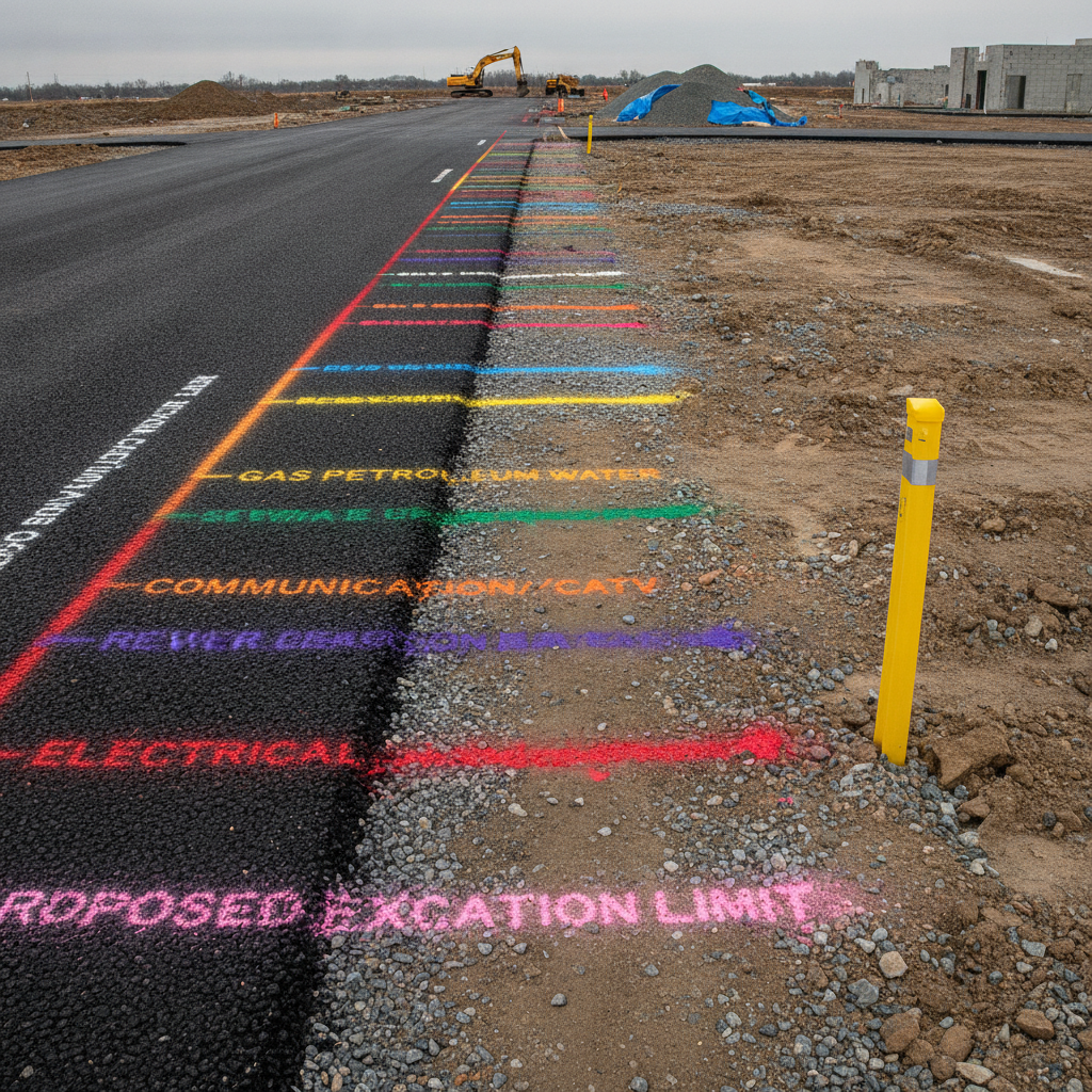
Underground pipe markers are systems and devices that identify the location and contents of buried utilities so crews can work safely and avoid strikes. In the USA, they combine surface signs, color codes, tapes, tracer wire, and locator targets to make hidden lines “visible.” The result: fewer outages, safer digs, and faster maintenance.
By Dante de Felice · Last updated: July 4, 2026
Overview
This complete guide explains what underground pipe markers are, why they matter, how they work, and how to implement them. You’ll get standards context, placement tips, tool recommendations, and real-world examples tailored to U.S. facilities and utility owners who need compliant, durable identification.
- What underground markers include and how they reduce damage risk
- Where ASME A13.1, ANSI Z535, and APWA colors fit
- Marker types: detectable tape, tracer wire, RFID/EMS, posts
- Placement, inspection, and documentation best practices
- Step-by-step program rollout with checklists
- Examples across plants, utilities, campuses, and pipelines
What Are Underground Pipe Markers?
Underground pipe markers are a coordinated set of visual and detectable cues that identify buried pipelines and utilities. They may include surface marker posts, color-coded paint or flags, detectable warning tape, tracer wire, and electronic markers so maintenance and excavation teams can find lines quickly and work safely.
When a line is buried, you lose the visual context you’d normally get from pipe labels. Underground pipe marking solves that by creating surface and subsurface signals that communicate location, path, and substance. The goal is fast, reliable detection before any soil is disturbed.
- Surface indicators: permanent marker posts, stake flags, or durable signs at crossings, property lines, and tie-in points.
- Subsurface indicators: detectable warning tape, tracer wire bonded to nonmetallic pipe, and electronic markers (RFID/EMS).
- Temporary locates: APWA color-coded paint for one-call tickets, often refreshed during projects.
VisionMarker supports the surface side with compliant, durable ANSI/ASME-aligned labeling and safety signage that complement subsurface systems. Together, they form a coherent identification program.
Why Underground Pipe Markers Matter
They prevent utility strikes, protect people, and keep operations online. Clear underground identification reduces excavation damage, speeds emergency response, and shortens maintenance windows. It also supports standards-aligned safety communication programs and strengthens regulatory readiness.
Striking a buried line can trigger service outages, environmental releases, equipment damage, and injuries. Even near-misses consume hours for investigation and repair. Effective identification frameworks give crews the confidence to plan, probe, and proceed with controlled excavation.
- Safety: Knowing what’s below reduces exposure to ignition sources, confined-space hazards, and high-pressure releases.
- Continuity: Avoids unplanned downtime that can ripple through production and logistics schedules.
- Clarity under stress: When seconds matter, visible and consistent markers make routes and shutoffs obvious.
- Accountability: Documented marker placement and inspections demonstrate diligence to auditors and insurers.
In our experience, facilities that formalize underground identification see faster permitting, fewer change orders for digs, and simpler turnover during contractor mobilization. The visibility and repeatability pay off across the asset lifecycle.
How Underground Pipe Identification Works
Underground identification combines permanent surface markers with subsurface detection methods. Crews use color codes, marker posts, detectable tape, tracer wire, and electronic markers to map lines, then verify routes with locators and safe-excavation techniques before digging.
The process blends planning, materials, and field methods into a closed loop you can audit and improve. Here’s the typical flow we recommend for U.S. industrial and utility owners:
- Baseline records: Confirm as-builts or create a preliminary GIS sketch of all buried assets.
- Select systems: Choose detectable tape, tracer wire, or electronic markers based on pipe material, depth, and risk.
- Surface control points: Install durable marker posts and signs at crossings, fence lines, and road approaches.
- Subsurface placement: Lay detectable tape above the line; attach tracer wire to nonmetallic pipe; place RFID/EMS markers at decision points.
- Color conventions: Use APWA colors for temporary locates and align surface sign design with ANSI Z535 principles.
- Verification: Sweep routes with an electromagnetic or RF locator. Probe and pothole as needed.
- Documentation: Capture photos, GPS points, and inspection notes. Update drawings.
- Training: Brief internal teams and contractors on reading your markers and escalation protocols.
Coordinating surface and subsurface signals is key: the best programs make it intuitive to follow a line from a post to the exact route beneath.
Standards and Codes That Apply
Underground programs draw on multiple U.S. conventions: APWA color codes for temporary locates, ANSI Z535 design principles for safety signs, and ASME A13.1 for aboveground pipe labeling. Together they support a consistent, legible system from surface to subsurface.
While underground markers aren’t governed by a single universal code, effective programs harmonize widely recognized frameworks so every cue reinforces the same message:
- APWA Uniform Color Code: Eight standard colors used by locators and excavators to mark temporary routes on the surface.
- ANSI Z535 system: Design language for signal words, color, and symbols on permanent safety signs and tags.
- ASME A13.1: Aboveground pipe identification that connects to buried segments at risers and penetrations.
- Facility safety signage: OSHA-style notice, caution, and danger signs increase clarity where lines surface or cross access routes.
| Color | Typical Utility |
|---|---|
| White | Proposed excavation |
| Pink | Temporary survey marks |
| Red | Electric power lines |
| Yellow | Gas, oil, steam |
| Orange | Communications/CATV |
| Blue | Potable water |
| Purple | Reclaimed water |
| Green | Sewer/drain lines |
For surface hardware, high-visibility posts and caps improve sighting along rights-of-way. For reference on visibility styles, see this example of marker post visibility for open terrain. For aboveground continuity, pair posts with durable labels from our Pipe Markers collection.
When designing permanent safety signage that complements buried utilities, we lean on the same principles outlined in our marking systems guide and the ANSI pipe labeling overview. This keeps typography, colors, and symbols consistent across your site.
Types of Underground Markers and Systems
You can combine several marker types: detectable warning tape, tracer wire on nonmetallic pipe, electronic marker balls/discs, and surface marker posts. Choose based on pipe material, depth, terrain, and criticality to create redundancy and improve locate speed.
Detectable and non-detectable warning tape
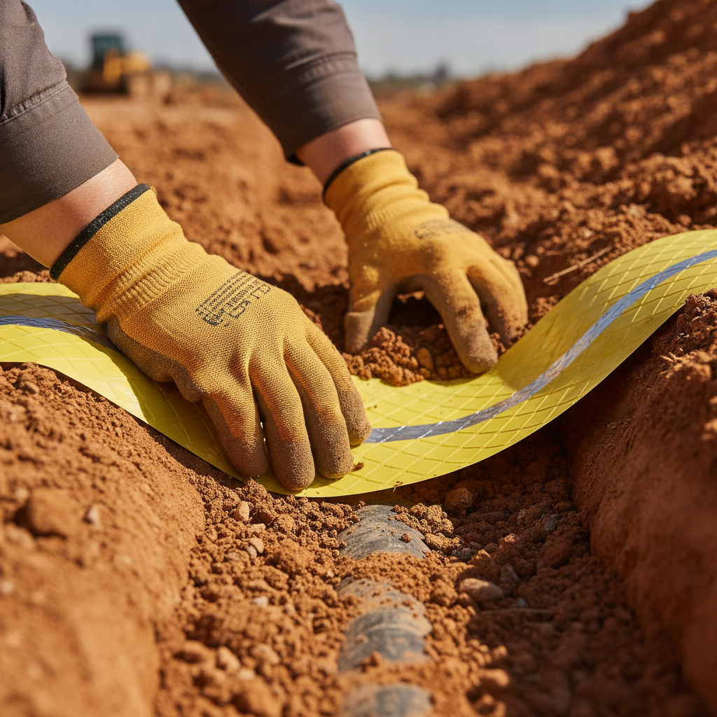
- Detectable tape: Plastic tape with a metallic layer laid 6–18 inches above the utility so a locator can pick it up before the bucket reaches the line.
- Non-detectable tape: Bright, printed tape for visual warning when trenching close to depth; often paired with tracer wire for detectability.
- Material considerations: Backings and films are often polymer-based; see representative polymer film examples for toughness and weathering context.
Tracer wire on nonmetallic pipe
- Purpose: Provides a conductive path for electromagnetic locators when pipe is PVC, HDPE, or composite.
- Practice: Bond the wire continuously with secure terminations at access points; document connections.
- Tip: Route test stations to safe, visible areas to speed verification.
Electronic markers (RFID/EMS)
- Use cases: Key decision points such as tees, valves, service saddles, and changes in direction or depth.
- Benefit: Precise point-location even in congested corridors; tags can encode asset metadata.
- Note: Color-tuned frequencies help distinguish utilities in mixed corridors.
Surface posts, signs, and curb markers
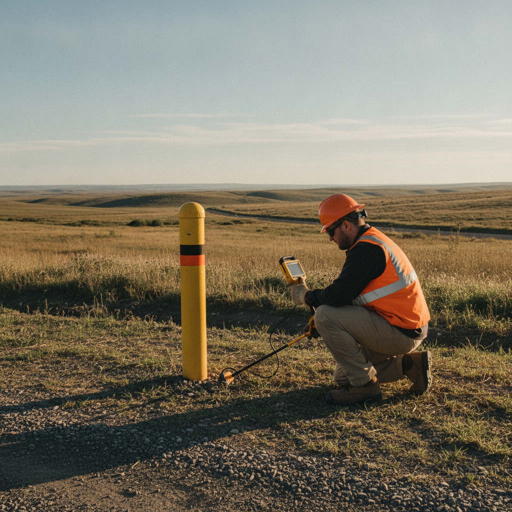
- Marker posts: High-visibility posts with legends, arrows, and emergency contact info where appropriate.
- Signs and decals: Use ANSI Z535-aligned design for clarity at roadway crossings and fence lines.
- Curb markers and disks: Permanent plates indicating service laterals, hydrants, or isolation valves.
Temporary locates: paint and flags
- One-call markings: APWA color paint and flags to show routes for the life of the ticket.
- Project control: Refresh markings as site conditions evolve so crews don’t guess.
Best Practices for Placement, Labeling, and Documentation
Design your system to be obvious from the surface and verifiable below. Standardize marker spacing, label every access point, document routes with photos and GPS, and audit the field reality annually so maps and markers stay in sync.
- Make it intuitive: A post should lead your eye to the route. Repeat markers where visibility drops (vegetation, snow, curves).
- Rational spacing: Use consistent intervals that reflect terrain, risk, and right-of-way access; tighten spacing at crossings.
- Continuity labeling: Where lines emerge, apply durable aboveground labels from our self‑adhesive pipe markers guide.
- Every decision point: Tag tees, valves, and transitions with electronic markers and photo-document them.
- Record once, verify twice: Capture GPS points and measurements at install, then recheck after backfill and again post-settlement.
- Close the loop: Update drawings and work orders so the next crew trusts what they see.
Label readability matters as much as location. Use clear signal words, legible type, and durable substrates. Our pipe markers on a roll overview describes material choices that hold up to UV, moisture, and chemicals at aboveground tie-ins.
Tools and Resources You’ll Use
Successful programs rely on locators, GPS/GIS, durable signs and labels, and repeatable procedures. Pair reliable equipment with standards-aligned signage and clear documentation for contractors and employees.
- Electromagnetic/RF locators: For tracer wire and metallic assets; choose models with depth and current measurement.
- Electronic marker readers: For RFID/EMS tags at tees, valves, and laterals.
- GPS/GIS apps: Capture points, photos, and notes; maintain revision history.
- Surface hardware: Posts, plates, and durable piping identification signage.
- Procedures: One-call ticketing, line-of-fire controls, and escalation steps for mismatches.
For background on common homeowner-facing water main risks that mirror industrial concerns, see this discussion of underground water mains. While residential, the principles of prevention and quick response echo across facility environments.
Need a fast, standards-aligned marking plan? VisionMarker supplies ANSI-certified safety signs and durable pipe identification that integrate with your underground program. Tell us your mediums, terrains, and risk points—we’ll help you standardize legends and materials for clarity.
How to Implement an Underground Marking Program
Treat underground marking as a managed lifecycle. Define scope, select materials, install consistently, verify with locators, document with photos and GPS, train users, and audit annually. The outcome is a reliable, repeatable system crews trust.
- Set objectives: Safety, damage prevention, response time, and regulatory readiness.
- Inventory assets: Build a line list with medium, diameter, material, pressure, and critical valves.
- Choose methods: Tape, tracer wire, electronic markers, and surface posts based on risk.
- Design signage: Use ANSI Z535 conventions for consistent legends and symbols.
- Standardize spacing: Define intervals by corridor type; closer at roads and utilities crossings.
- Field install: Supervise trench crews; capture photos before cover.
- Verify routes: Sweep with EM/RF locators; pothole at conflicts.
- Update records: Store GPS, photos, and inspection forms in your CMMS or GIS.
- Train: Onboard contractors; post quick guides at job-start trailers.
- Audit: Annual walkdowns and spot checks after major work orders.
Case Studies and Practical Examples
Here are real-world scenarios that show how integrated underground pipe markers reduce risk and speed work. Each example highlights a challenge, the chosen mix of markers, and the measurable operational benefit.
- Manufacturing campus: Mixed gas, water, and compressed air. Solution: tracer wire on HDPE air lines, detectable tape on gas, posts at road crossings. Result: new tool install completed without utility conflicts.
- Water utility: Long runs across easements. Solution: marker posts every visible bend, EMS markers at tees, blue curb markers at hydrants. Result: crews located valves rapidly during a main break.
- Hospital: Buried medical gas laterals. Solution: electronic markers at each isolation valve, standardized legends at risers. Result: faster emergency isolation drills.
- Pipeline ROW: Open country with vegetation. Solution: high-visibility posts and regular patrol. See representative marker visibility styles. Result: better aerial sighting and fewer encroachments.
- Data center: Congested utility corridors. Solution: color-coordinated EMS markers and meticulous GIS photos. Result: no-dig zones clearly defined for expansions.
- Airport operations: Security-sensitive areas. Solution: tracer wire continuity tests logged quarterly; conspicuous but compliant signage at fence lines using ANSI Z535 cues. Result: fewer access delays.
- Power plant: High-pressure steam condensate returns. Solution: detectable tape and posts at expansion joints; aboveground roll markers at risers. Result: thermal maintenance without misroutes.
- School district: Seasonal digs for athletics fields. Solution: simple tape over water and gas, APWA paint for each ticket. Result: consistent contractor expectations.
- Distribution center: Frequent rack moves with footings. Solution: enhanced one-call procedures and refreshed surface plates. Result: avoided a telecom strike during peak season.
- Refinery: Dense pipe networks and risk hotspots. Solution: EMS markers at critical valves; signage integrated with plant labeling standards. Result: quicker navigation for mutual-aid responders.
- Municipality: New subdivision services. Solution: tracer wire continuity testing pre-turnover; curb markers for laterals. Result: faster locates for future repairs.
- Contractor jobsite: Compressed timelines. Solution: pre-task briefs using photos of posts, flags, and tape. Result: crews aligned on hazards before excavation.
Maintenance and Audits That Keep You Ready
Schedule inspections, confirm locator readability, and fix gaps quickly. Pair field walkdowns with record updates so posts, tapes, and electronic markers match your drawings. Treat changes after projects as a trigger for an immediate mini-audit.
- Quarterly spot checks: Verify post visibility, replace faded decals, and resecure loose caps.
- Annual program audit: Locator tests on tracer wire circuits; sample EMS tag reads; GPS accuracy review.
- After-action updates: Any excavation or repair triggers a quick re-mark and documentation pass.
- Training refreshers: Short toolbox talks on reading markers and resolving mismatches.
- Supply readiness: Keep replacement posts, decals, and aboveground labels from our Pipe Markers collection stocked for quick fixes.
If your site regularly adds or reroutes services, fold underground checks into your management of change workflow. It’s the simplest way to prevent stale maps and confusing field conditions.
Key Takeaways
Underground pipe markers work best as a coordinated system. Combine surface posts, ANSI/ASME-aligned legends, and subsurface detection, then verify with locators and keep records current. The payoff is safer work, fewer strikes, and faster response when conditions change.
- Build redundancy: surface visibility plus subsurface detectability.
- Standardize legends using ANSI Z535 cues tied to ASME A13.1 content naming.
- Document everything with photos, GPS, and inspections.
- Train contractors to read and trust your system before they dig.
- Refresh after every project to keep reality and drawings aligned.
Frequently Asked Questions
These quick answers address how underground markers are used on U.S. sites, what materials to choose, and how they integrate with aboveground labeling and safety signage.
What’s the difference between detectable tape and tracer wire?
Detectable tape is a colored warning strip with a metallic layer placed above a line so locators can find it before digging reaches the utility. Tracer wire bonds to nonmetallic pipe to create a continuous conductive path for electromagnetic locators. Many programs use both for redundancy.
Do underground pipe markers replace aboveground labels?
No. Underground systems complement aboveground labels. Use ANSI/ASME-aligned legends at risers, penetrations, and equipment, then reinforce routes with posts, tape, tracer wire, and electronic markers so crews can trace lines end to end.
How often should we inspect underground markers?
Perform quarterly spot checks for visibility and damage, and complete an annual program audit that verifies locator readability, electronic marker function, and record accuracy. Reinspect immediately after any excavation or repair affecting the corridor.
Which standards guide sign design for marker posts?
Use ANSI Z535 principles for signal words, colors, and symbols, and connect content naming to ASME A13.1 for consistency with your aboveground pipe identification. This keeps language aligned across surface and subsurface markings.
Conclusion
Underground pipe markers turn buried assets into readable systems. With consistent posts, labels, detectable elements, and good records, crews work faster and safer—and you stay inspection ready. Start with clear standards, then implement and audit with discipline.
- Next steps: Map assets, choose your marker mix, set spacing rules, and standardize legends.
- Use VisionMarker’s resources—ANSI pipe labeling, self‑adhesive markers, and marking systems—to keep design consistent.
- Keep a small stock of replacement posts and labels so fixes happen the day issues are found.
Ready to build a consistent, durable, standards-aligned underground marking program? Let’s talk about your corridors, mediums, and risk points—our team can help you finalize legends, material choices, and inspection checklists.